A RetroPie (or similar) controller for £5?!
I recently found myself in Poundland seeing what a humble pound coin could get me, aside from the usual cables, chargers and similar accessories I buy… seriously, they work fine and are only £1/£2, not to mention their chargers are far better than cheap ones you’d find on ebay! Check out this video from bigclivedotcom on the subject.
As I was browsing, I happened upon the £5(!) electronics/games section. There were a few XBOX360 games and such, but what caught my eye was this;
 I forgot to take a photo at the shopIt is a Gioteck ‘Turbo Controller’ for the Nintendo Classic Mini. It looks basically like a NES controller with turbo buttons. Considering my RetroPie setup at home, but having no idea of the protocol/connector it used, I decided it was worth the sacrifice of £5 to find out if I could make it work. You can also get these controllers from the likes of argos/ebay (for £5.99, the horror!).
I got it home, opened it up and saw the Nintendo ‘nunchuck’ style plug on the (surprisingly long) cable. This was a good start and I figured that it probably uses the same protocol as the Nunchuck or the Wii Classic Controllers and similar that use the same plug. Both of these use the I2C protocol and there are various libraries out there to allow them to be use with Arduino’s and compatible micro-controllers.
I was hoping there would be something similar for the Raspberry Pi, given it has an I2C bus built in, but unfortunately the only information I could find was on drivers for the Wii controller with a Nunchuck or Classic Controller connected to it, connected to the Raspberry Pi over bluetooth, which was no use to me as I don’t own a Wii controller.
So I decided to write my own ‘driver’ for it (more of a daemon actually!) and here is how I did it;
First thing I had to do was crack it open to see if I could find the pinout. Mercifully it was printed right on the board, along with several test points I plan to investigate later. I2C devices generally use four wires VIN (Power, 3.3v) GND (Ground), SDA (Data) and SCL/CLK (Clock).
In this case, VIN is red, GND is black, SDA is green and CLK is white.
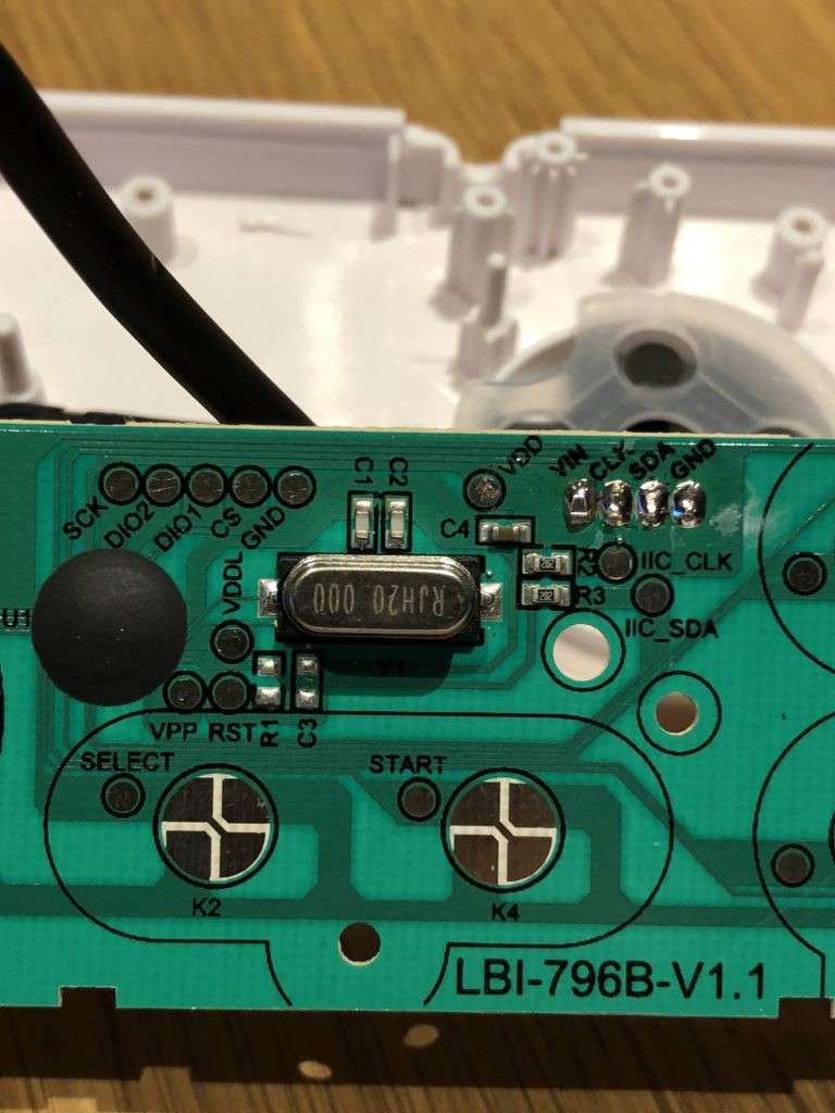 Controller PCB with connections labeledGiven that this experiment was so cheap, I simply cut off the nunchuck style plug to expose the wires and I then attached my own pin sockets/plug for easy connection to a Raspberry Pi or other devices.
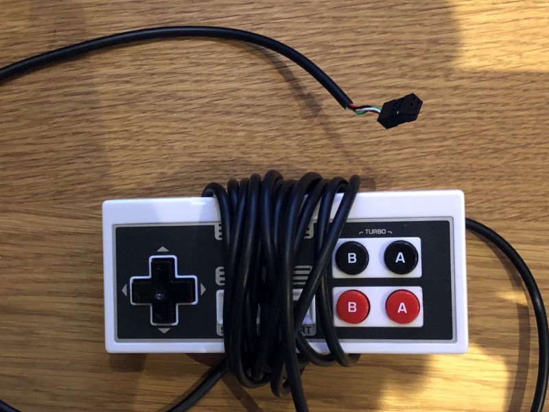 Controller with new Raspberry Pi compatible plugAdding the plug made it very easy to connect and disconnect it from the various raspberry Pi’s I used for testing, namely a Raspberry Pi 3 I use to run RetroPie in my lounge room, and a Raspberry Pi 0W that I used for headless testing/development.
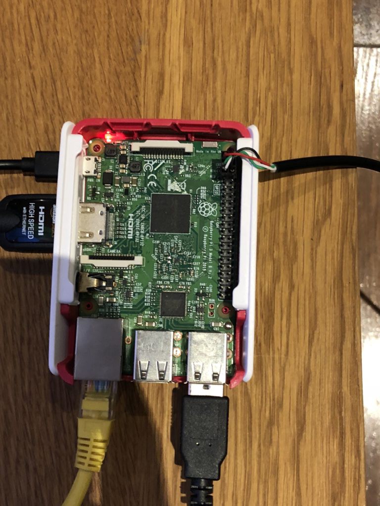 Connected to the Raspberry PiIf you didn’t want cut it up, you can get you could grab a ‘Nunchucky’ from adafruit and solder wires and an appropriate plug to that, or scavenge sockets from a broken system.
Once I had the new plug on it, I connected it to an Arduino nano to do some testing. I initially tried the WiiClassicController library to see if it used the same protocol as the Nunchuck/Classic Controller and luckily for me, it did. So now I had to work out a way to get that data into a useable form on the Raspberry Pi using its I2C bus.
Ideally you would write a kernel module in C for this, but given my very limited knowledge of C and desire to get it running quickly I had to pick something else. I am most comfortable with Java so my my first attempt was to write a simple app that used the PI4J and Robot libraries to take the data from the I2C bus and turn it in to keyboard commands. This was very quick and easy to write, but unfortunately was a failure as Robot on linux requires X11 to be running for it to work, and RetroPie does not use X11.
I looked around, and a good way to achieve keyboard emulation at a lower level was with the ioctl call, and there happens to be an wrapper for it in NodeJS. I am not brilliant with JS but I have written node app’s before and figured it was going to be easier than learning C (which I do want to do at some stage!)
My first attempt was using the virtual-input library, but nothing I did would make it work with the Raspberry Pi. I could get it work fine on an ubuntu VM to send keystrokes, but never on the Pi.I saw that it was used in another project, node-virtual-gamepad which is a really cool project. So I tried it and it and worked fine on the Pi.
I then had a look through the source to see if I could extract its virtual keyboard code for use in my own project and after much wrangling, I got it to work! I used evtest to detect the virtual keyboard codes as they were sent by the virtual keyboard code.
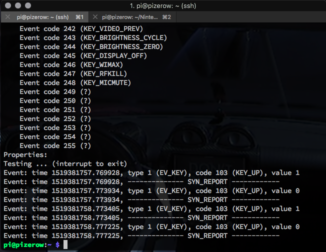 evtest runningThe next thing to do was integrate the keyboard code with the I2C library to come up with some sort of daemon that would interpret the commands sent from the controller over I2C into keypresses on the virtual keyboard, thus controlling the game.
There was also code for emulating joysticks/gamepads which I do plan to build in to the daemon, so that you can choose to emulate a keyboard or gamepad depending on your needs. But the first order of business was to get it working as a virtual keyboard.
Once I had both portions working, both I2C reading and virtual keyboard, i was able to combine them to build the daemon that will run in the background and interpret the data from the controller in to keyboard presses to control the Raspberry Pi.
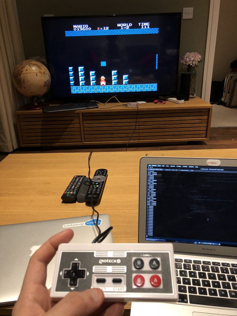 Testing it out with a bit of MarioThe code and is available on my github here, along with instructions on how to setup and use it. If you want more detail on how I built it, read on.
Once I had both the virtual keyboard and I2C code working combining them was relatively straightforward, but there were a few gotchas.
- As I learned from the Arduino library, the gamepad sends data in ‘packets’ of 6 bytes
- When there is no buttons pressed, the result always begins with a 0x0 (0) with the packet looking like this (decimal);
- [ 0, 0, 128, 128, 255, 255 ]
- The gamepad sends a ‘heartbeat’ packet of 6x 0xFF (255) byte values every ~8 seconds and a randomly times packet that begins with 0x1 (1), these look like this (decimal);
- [ 1, 0, 164, 32, 1, 1 ] [ 255, 255, 255, 255, 255, 255 ]
- In the linux event subsystem when a key is pressed a 1 is sent and it will remain pressed until a 0 is sent for the same key, you can send multiple 1’s and 0’s at once
- All 8 buttons are handed by the last two bytes in the array (5 and 6) and some buttons when pressed together send a new code if they are on the same byte. I had to test and map these out.
- I needed to ensure that 2 buttons can be pressed at a time in order for the controller to be useful Below is a table of the keys to their ‘bytes’ that I am using to detect keypresses;
Button Position Hex Dec D-pad Up Byte 5 0xFE 254 D-pad Down Byte 4 0xBF 191 D-pad Left Byte 5 0xF3 253 D-pad Right Byte 4 0x7F 127 Start Byte 4 0xEF 239 Select Byte 4 0xFB 251 A Byte 5 0xEF 239 B Byte 5 0xBF 191
Given that some buttons share the same byte (such as A&B) they give different results if pressed at the same time. Below is a table of the ‘Combination’ bytes and positions;
Combination Position Hex Dec A & D-pad Up Byte 5 0xEE 238 B & D-pad Up Byte 5 0xBE 190 Select & Start Byte 4 0xEB 235 A & D-pad Left Byte 5 0xED 237 B & D-pad Left Byte 5 0xBD 189 D-pad Up & D-pad Left Byte 5 0xFC 252 D-pad Down & D-pad Right Byte 4 0x3F 63 D-pad Down & Start Byte 4 0xBB 187 D-pad Down & Select Byte 4 0xAF 175 D-pad Right & Select Byte 4 0x6F 111 D-pad Right & Start Byte 4 0x7B 123 A & B Byte 5 0xAF 175
Once I had this information, the code itself is fairly simple.
It polls the controller every 10ms (this can be changed) for the 6 byte array. From that I build JSON object containing each button and its state (0 or 1). I then check this against the last iteration to see if its changed to detect a change in state of a button, if its changed I then set the key high or low using the virtual keyboard library, at the end of the iteration i pass the current button states in to the ‘old’ iteration variable and start again. Only if the key has changed from one iteration to the next do I send a key event to change its state in the events subsystem.
The daemon is designed to be run in the background upon boot of the system to register events from the controller and pass them to the virtual keyboard. I also noted that the controller can be connected and disconnected while the daemon is running with no ill effects.
Let me know if you found this useful or interesting, or if you have any suggestions on improving it!
